ARCH 2613 Structural Systems // Cornell University School of Architecture, Art, and Planning
Spring 2021 // Professor: Mark Cruvellier
In this semester-long model, We were tasked to closely examine an existing building to see how it works in terms of their mechanical function but also how they can be related to conceptual design ideas and to form and space-making objectives.
Group Project with Imari Monroe and Grace O'Malley
Architect: Estudio Lamela, Rogers Stirk Harbour + Partners
Location: Madrid, Spain
Year Completed: 2005
Area: 470,000 m
Engineers: Structural - Anthony Hunt Associates, TPS with OTEP, HCA Services
Owners: ENAIRE
Background Information:
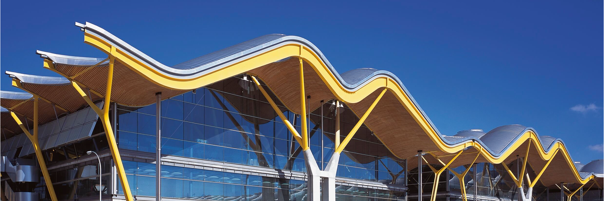
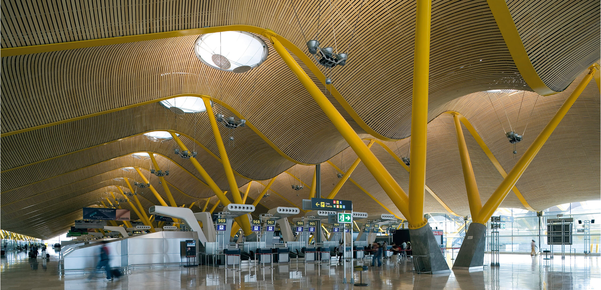
The Madrid Airport was first constructed in 1925 by Antonio Lamela. Terminal 4, built in 2005, became an addition to the airport after an increased growth in traffic. The addition catered to Southern Europe for a main connection between Europe and Latin America.
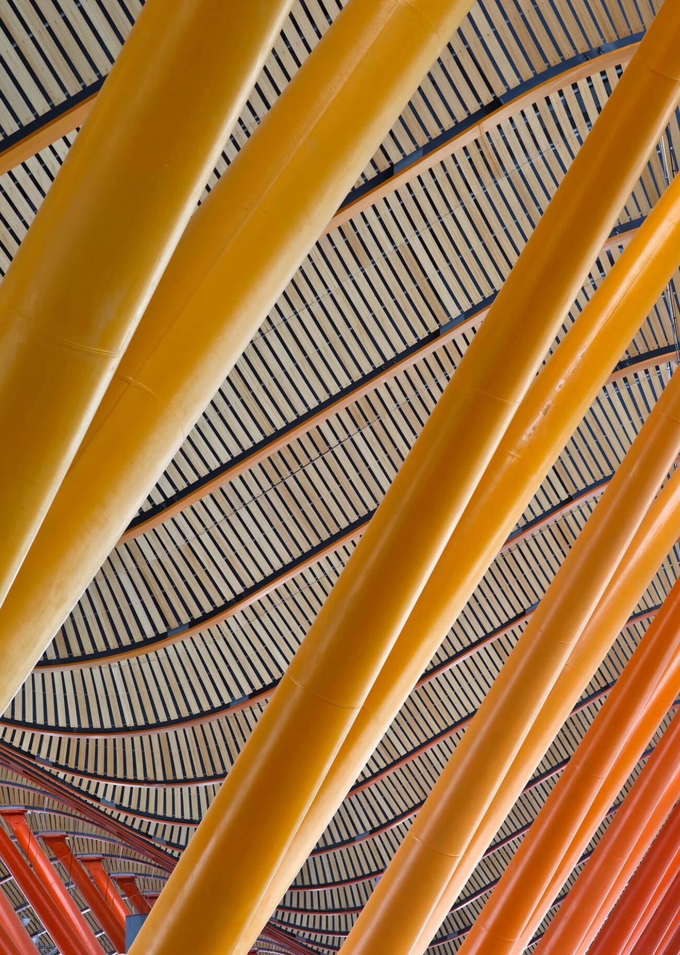
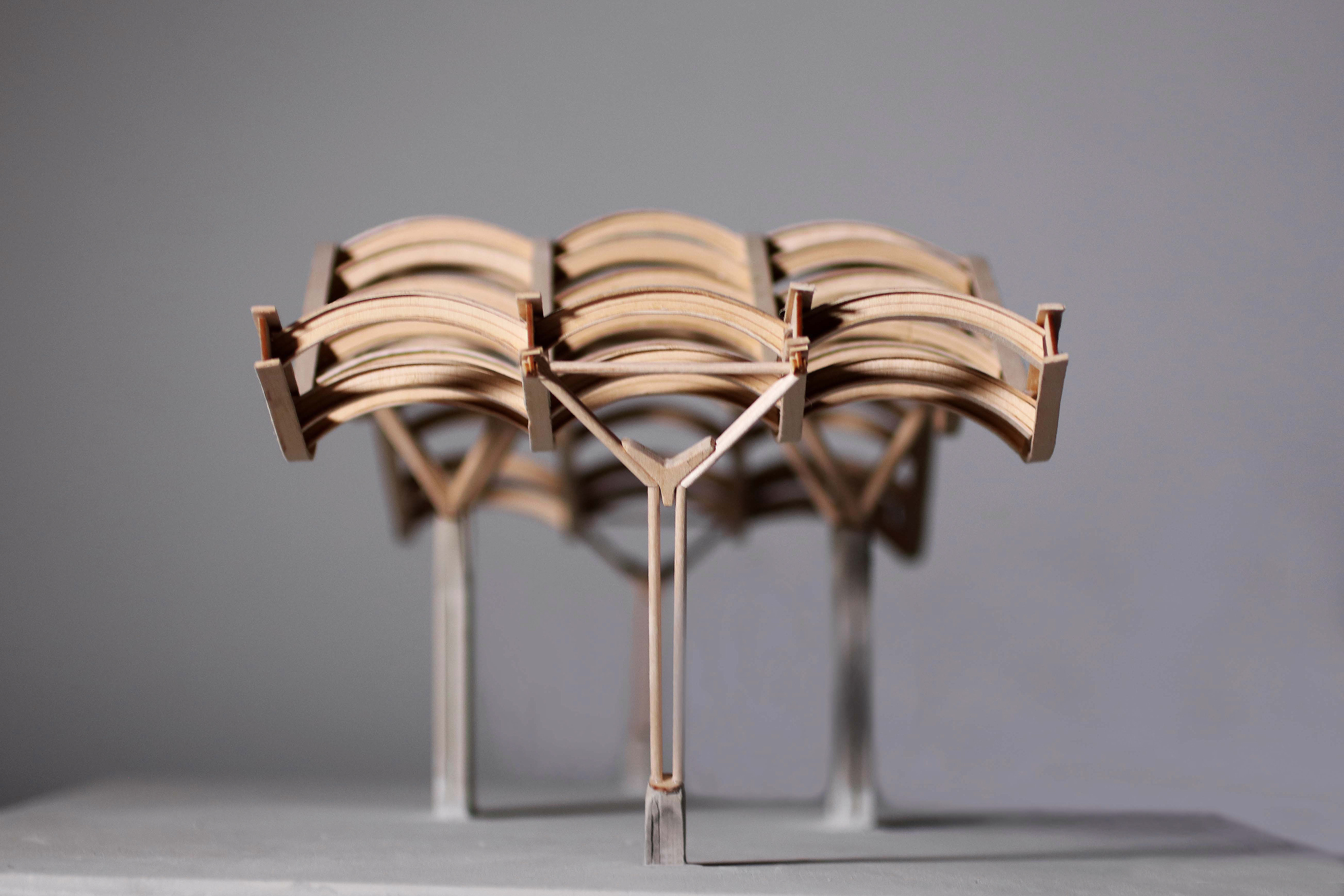
The architects wanted to create an undulating roof design that embodies the flexibility and movement of travel. The almost bird-like wings are suspended off of the floor by the steel beams. The roof ripples in both planar directions and openings are located between the steel beams to offer natural light. These intermitent skylights allow for the reduction of energy consumption and ultimately a cost reduction in maintenance. Our proposal highlights the way the roof structure sits in a sectional model that represents the core of the Madrid airport due to the extremely drawn-out and repetitive nature of the building.
The interior structure of the terminal is broken up into three volumes that have what some call “canyons” that allow for natural light at various levels. The design highlights passive environmental systems, while also maximizing transparency and views from the airport. The facades are protected by deep roof overhangs and shading on the exterior.
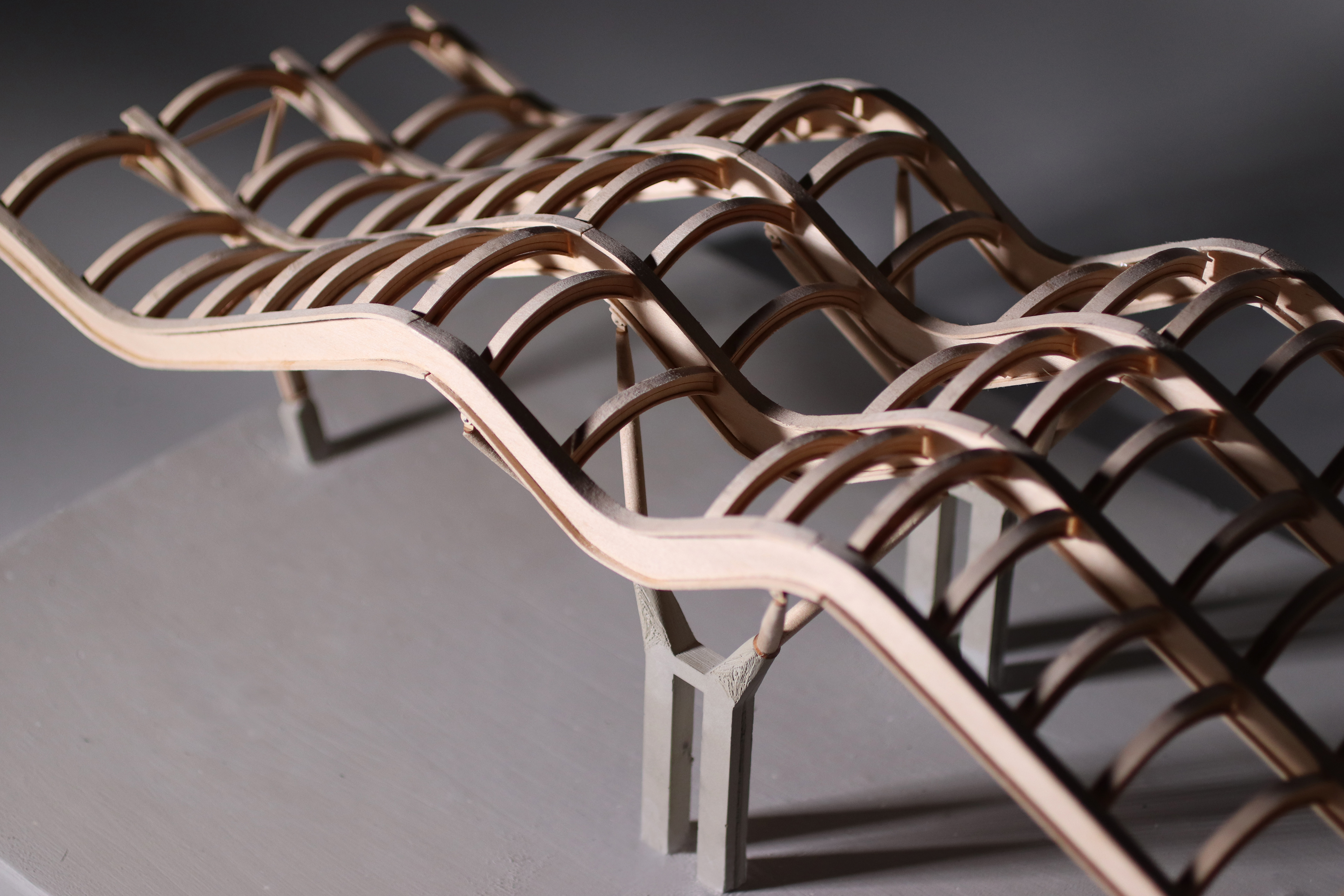
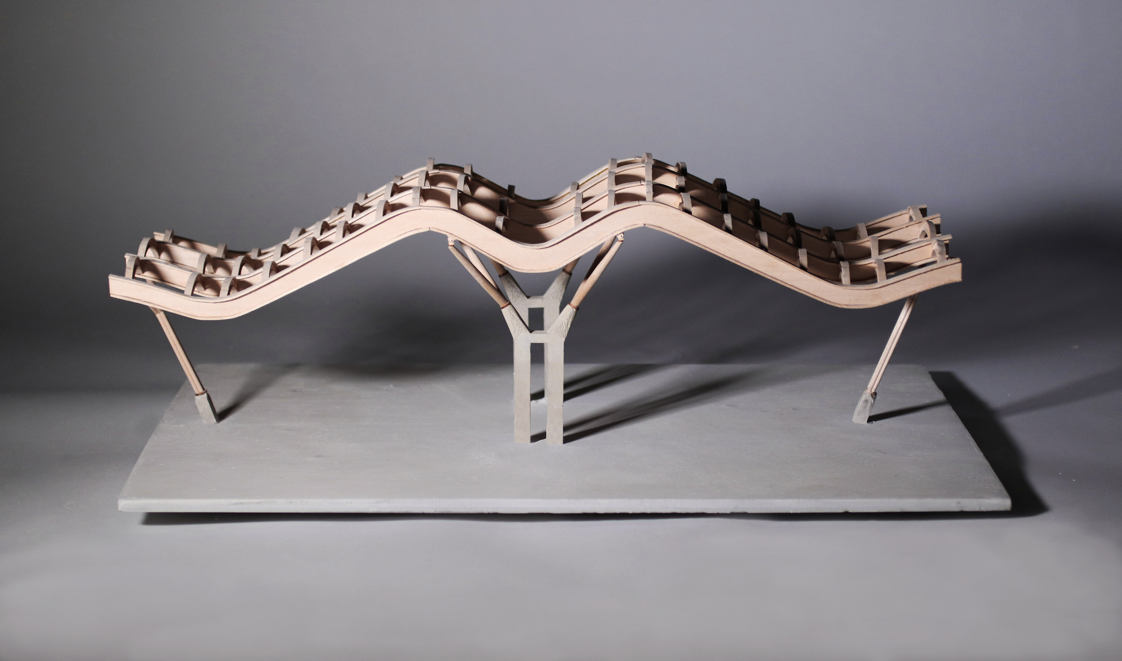
Final Model
Structural System and Analysis
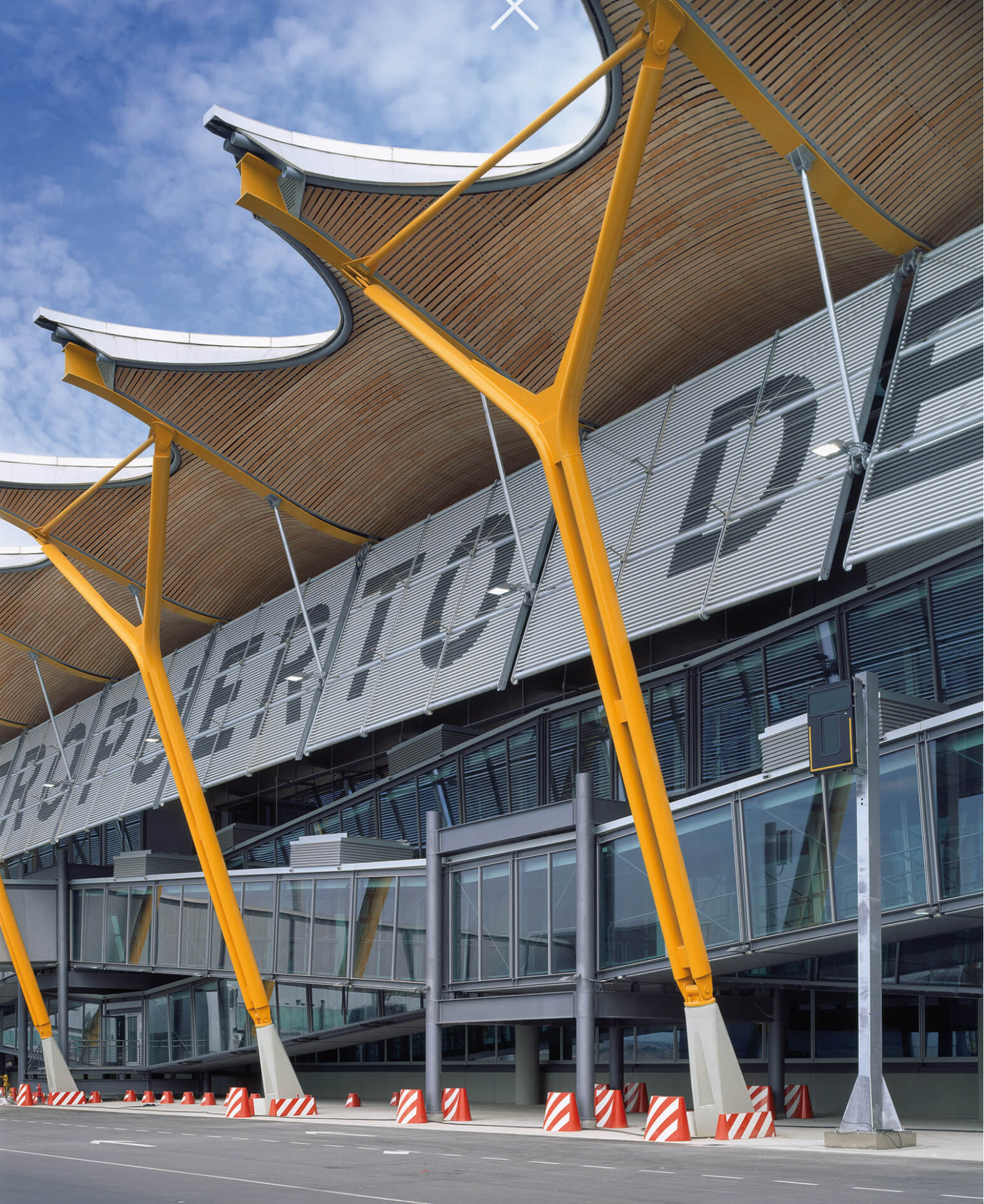
Terminal 4 consists of post-stressed concrete beams and columns that also have metal supports branching off to give the main roof beams support. The facade of the building ironically is an essential part to the support of the building overall. The curtain wall provides stability by bracing the roof structure and concrete beams connection. This is acheived through a set of steel rods that are positioned around the perimeter of the building.
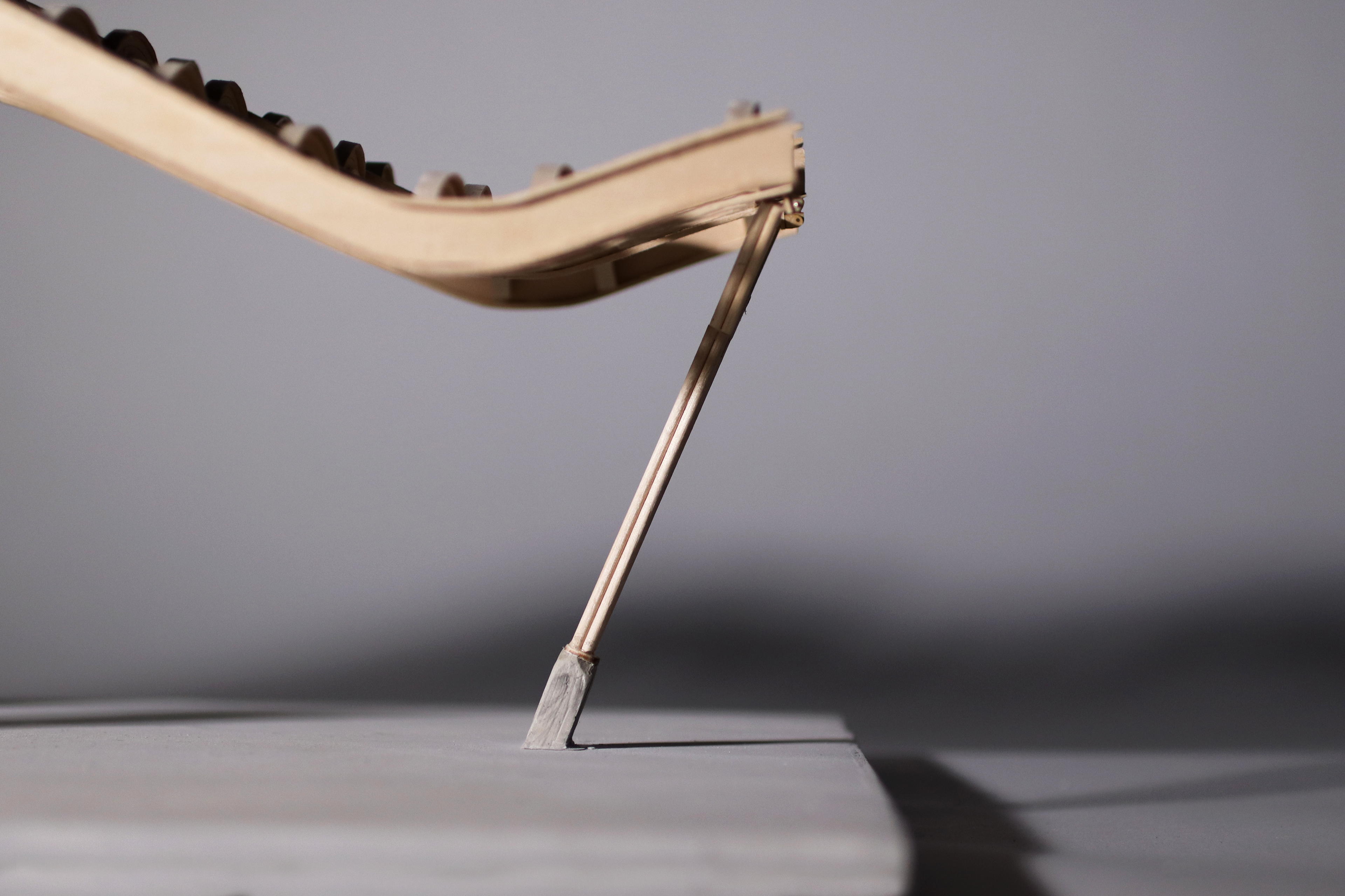
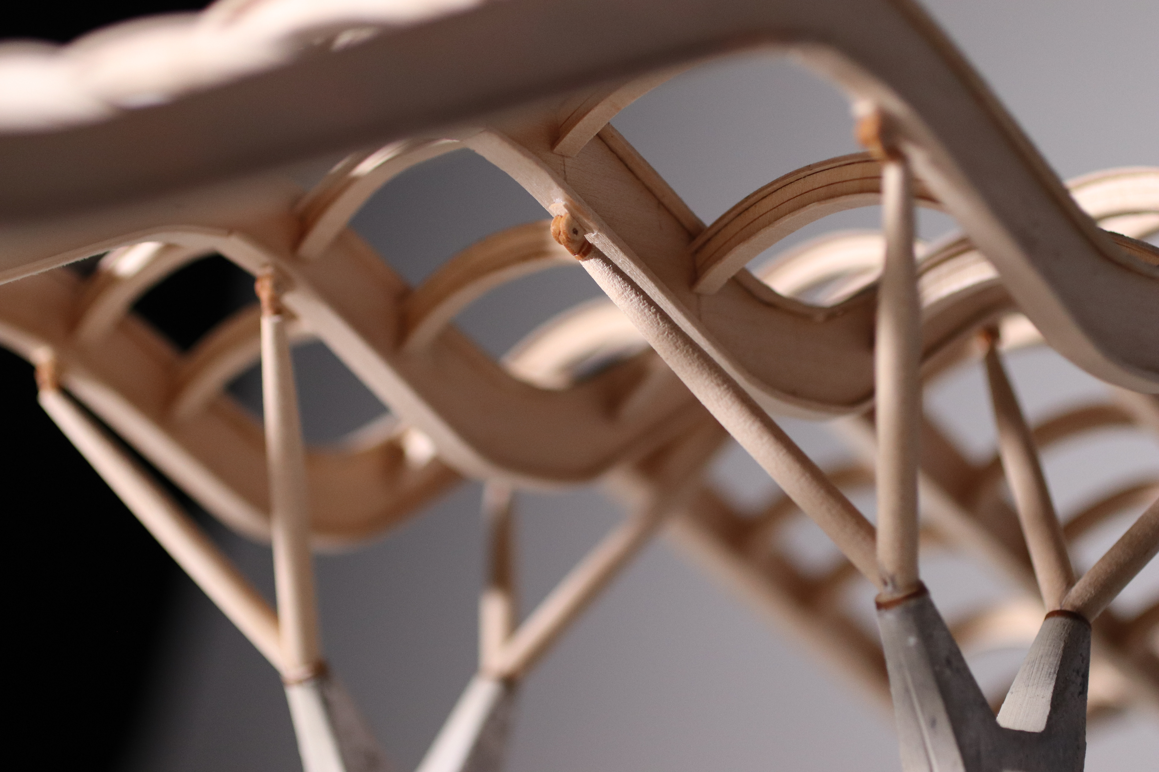
Beams - The main beams in Terminal 4 are about 72 meters and are spaced approximately 9 meters apart. These bays that are held up by a series of diagonal columns to hold up the load. In order to achieve the high curvature and combat stress increase of the wings, S355 J2G3 steel was used in specific areas. These 218.7 Ft long bays need its main support in the center of the wing while small support anchor at the end also assist to secure the beams in place. These diagonal columns are secured in place on the floor with concrete bases that allow security and stability.
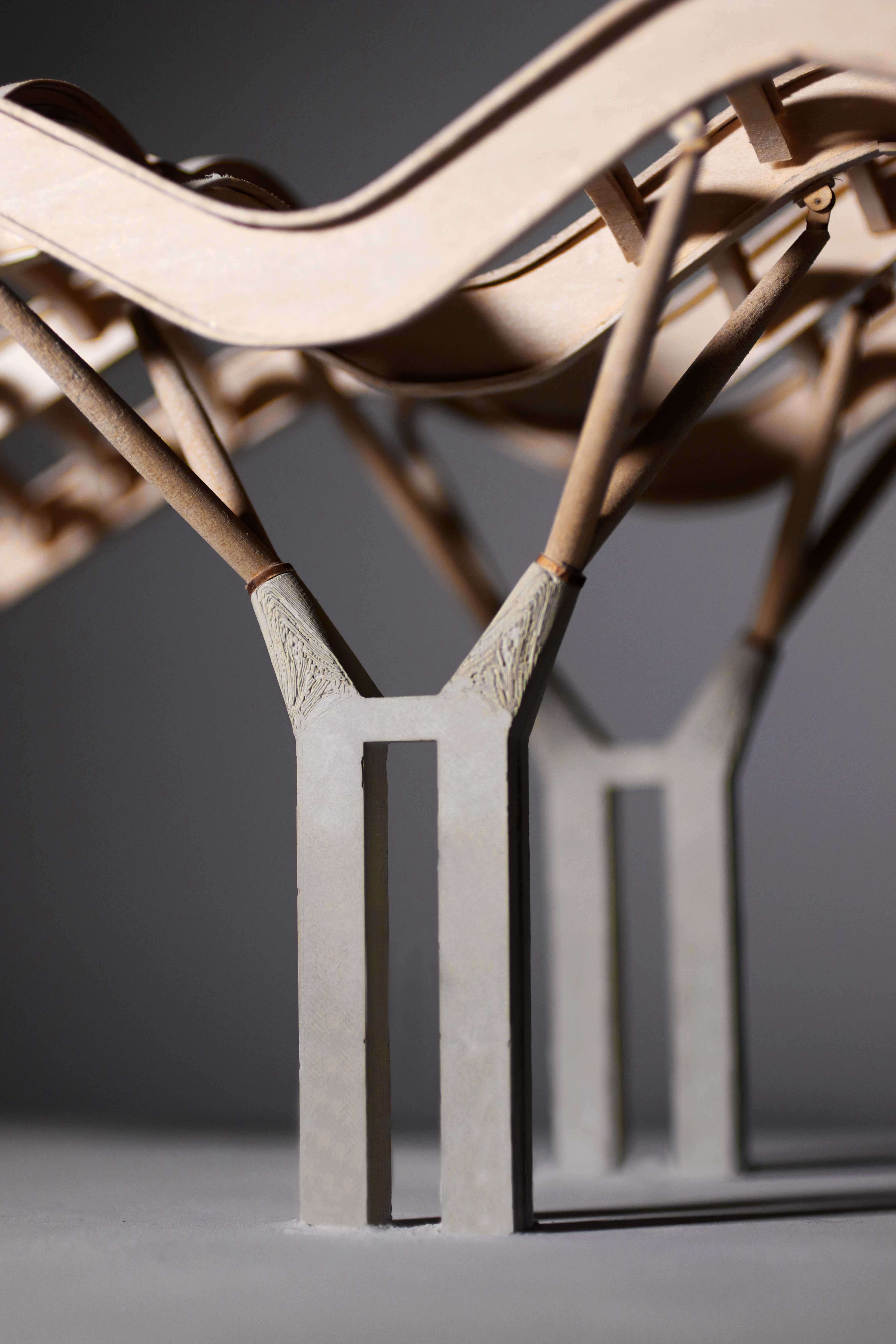
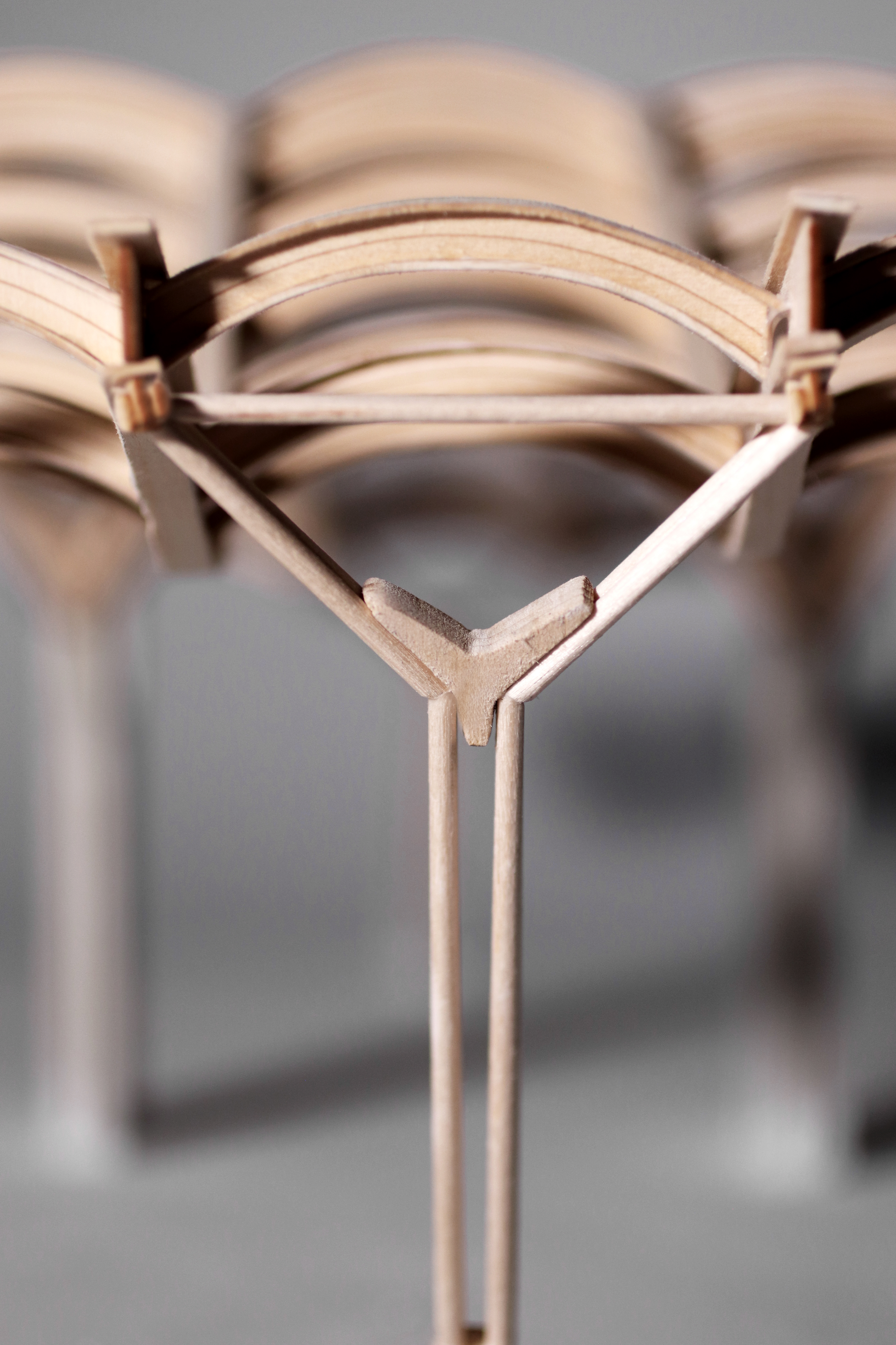
V and Y Supports - Throughout the main beams there are two center and two side support points that lean on metal details that are then embedded into concrete blocks. The Y-shaped steel support system allows for bending and compression stress along the two arm-like frames. Not only do the y-shaped frames provide extensive support, they also minimally obscure the viewers perception of the space. These lateral loads are dispersed through 4 different columns to allow rotational and structural support.
Construction Plan
Roof System:
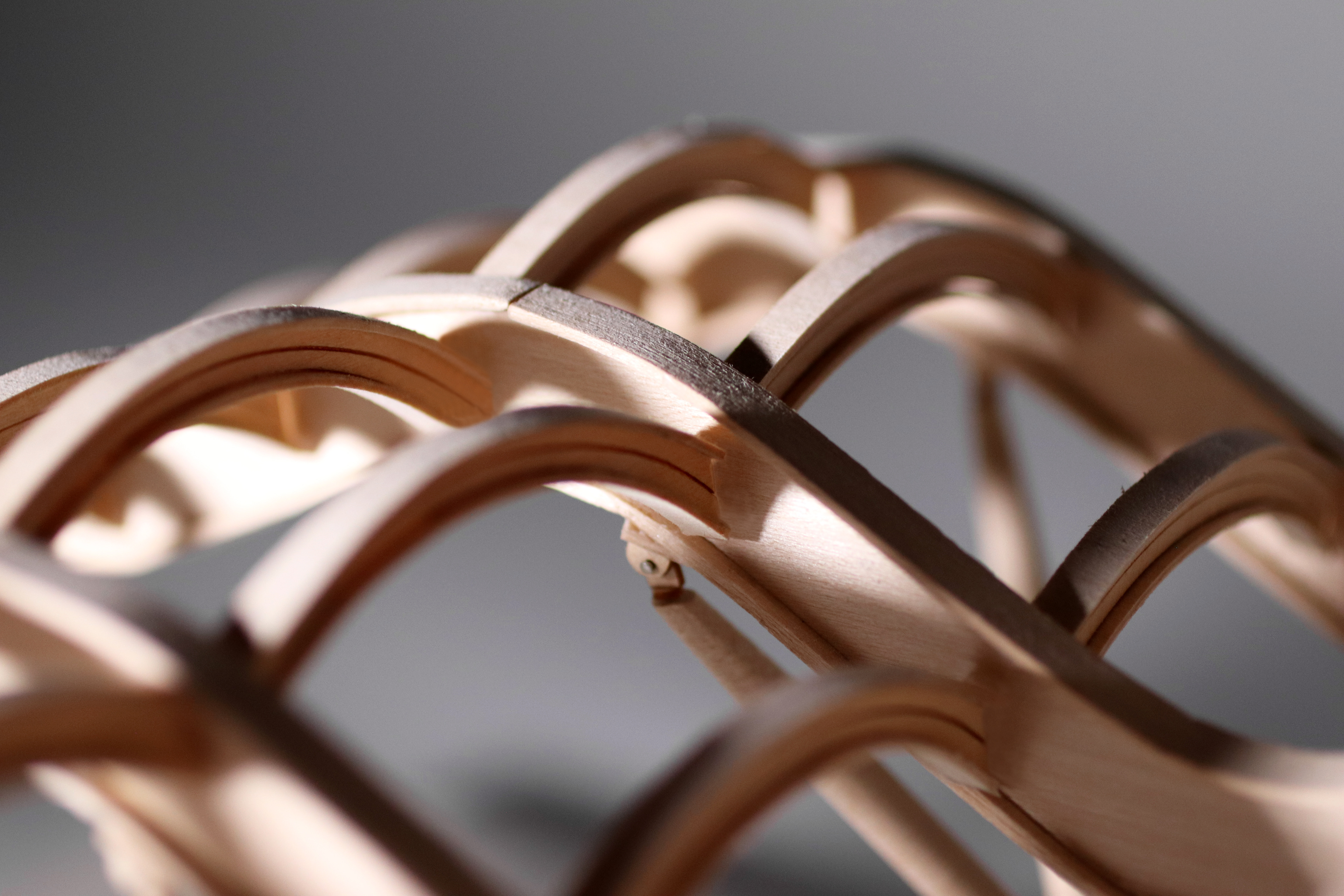
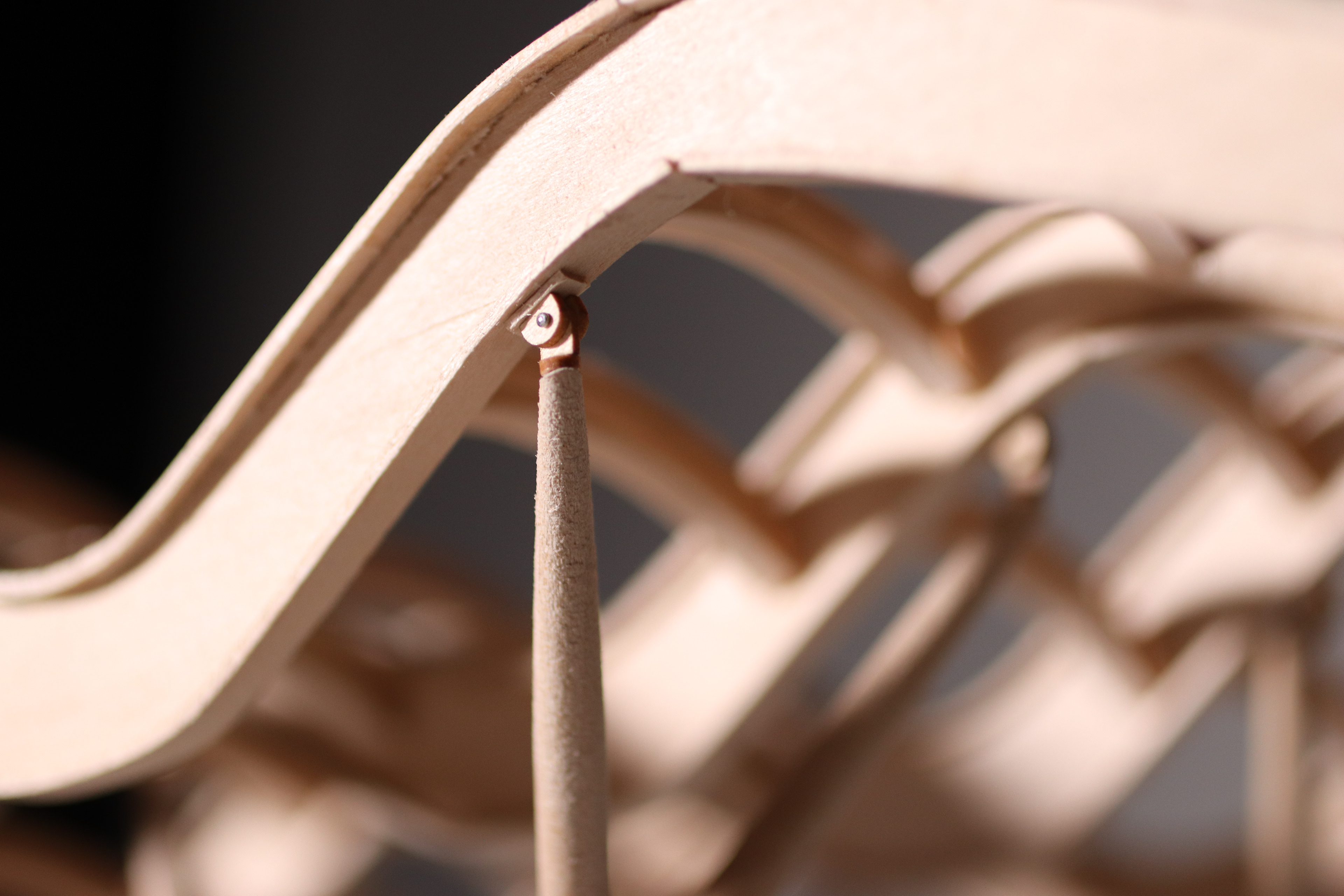
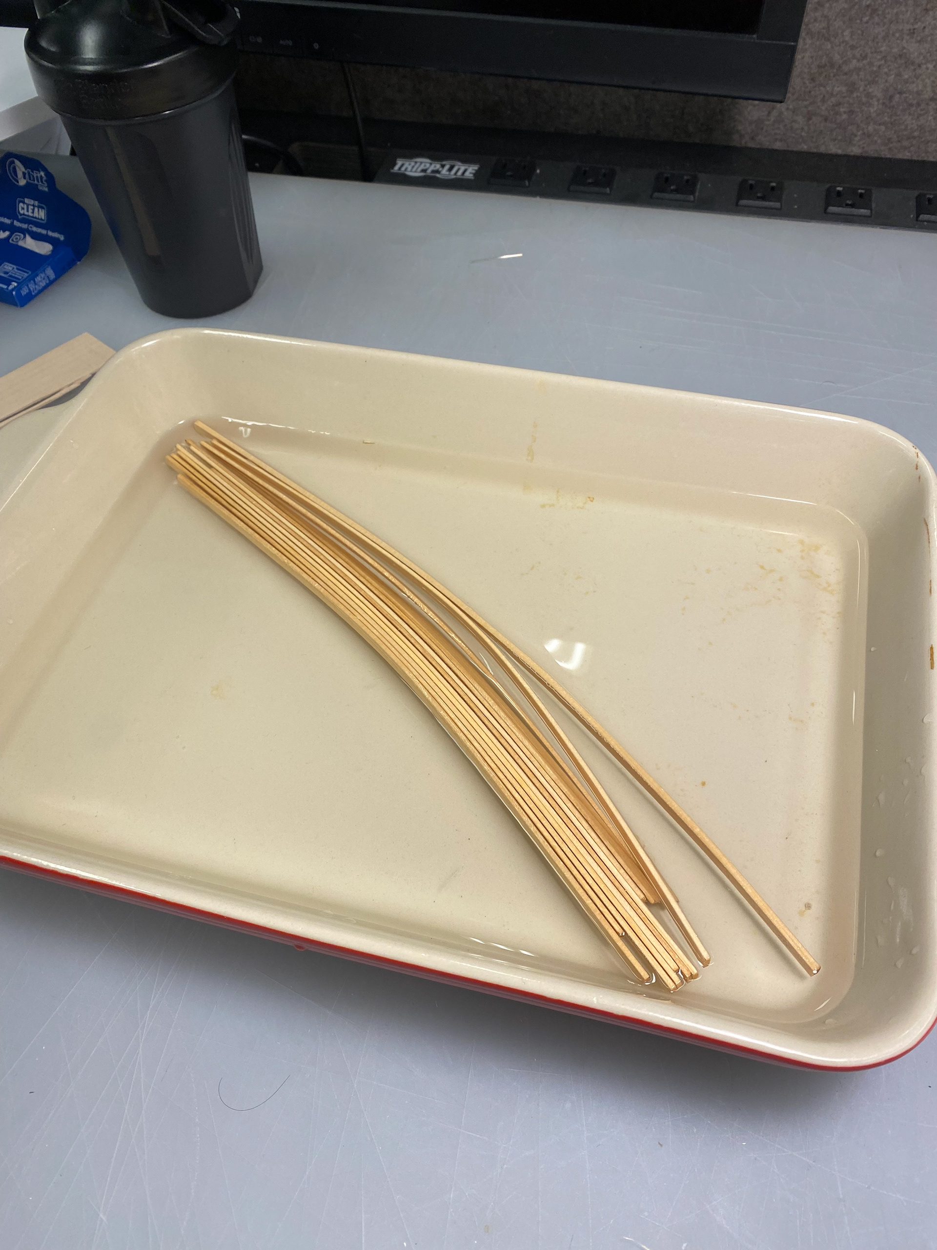
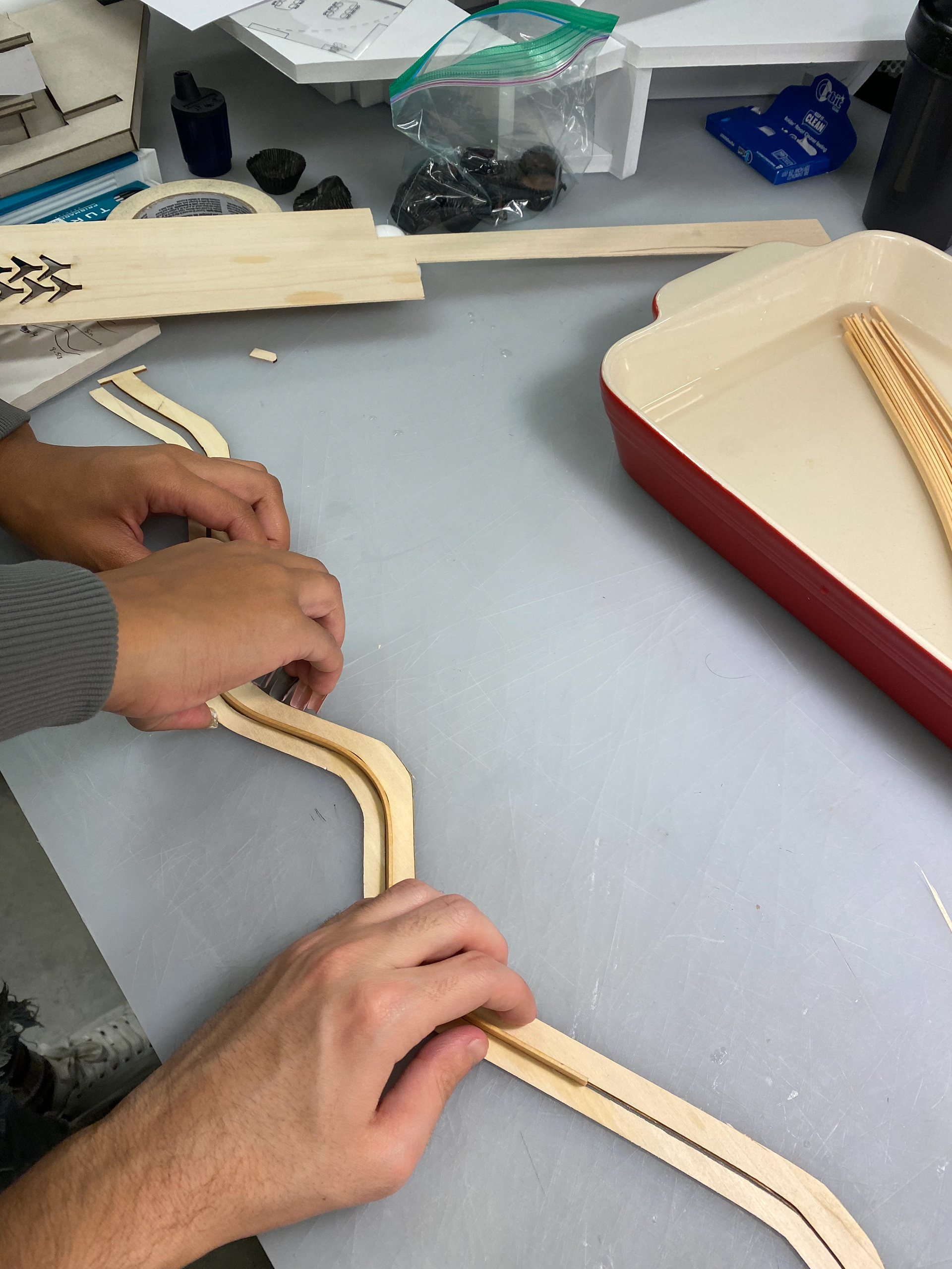
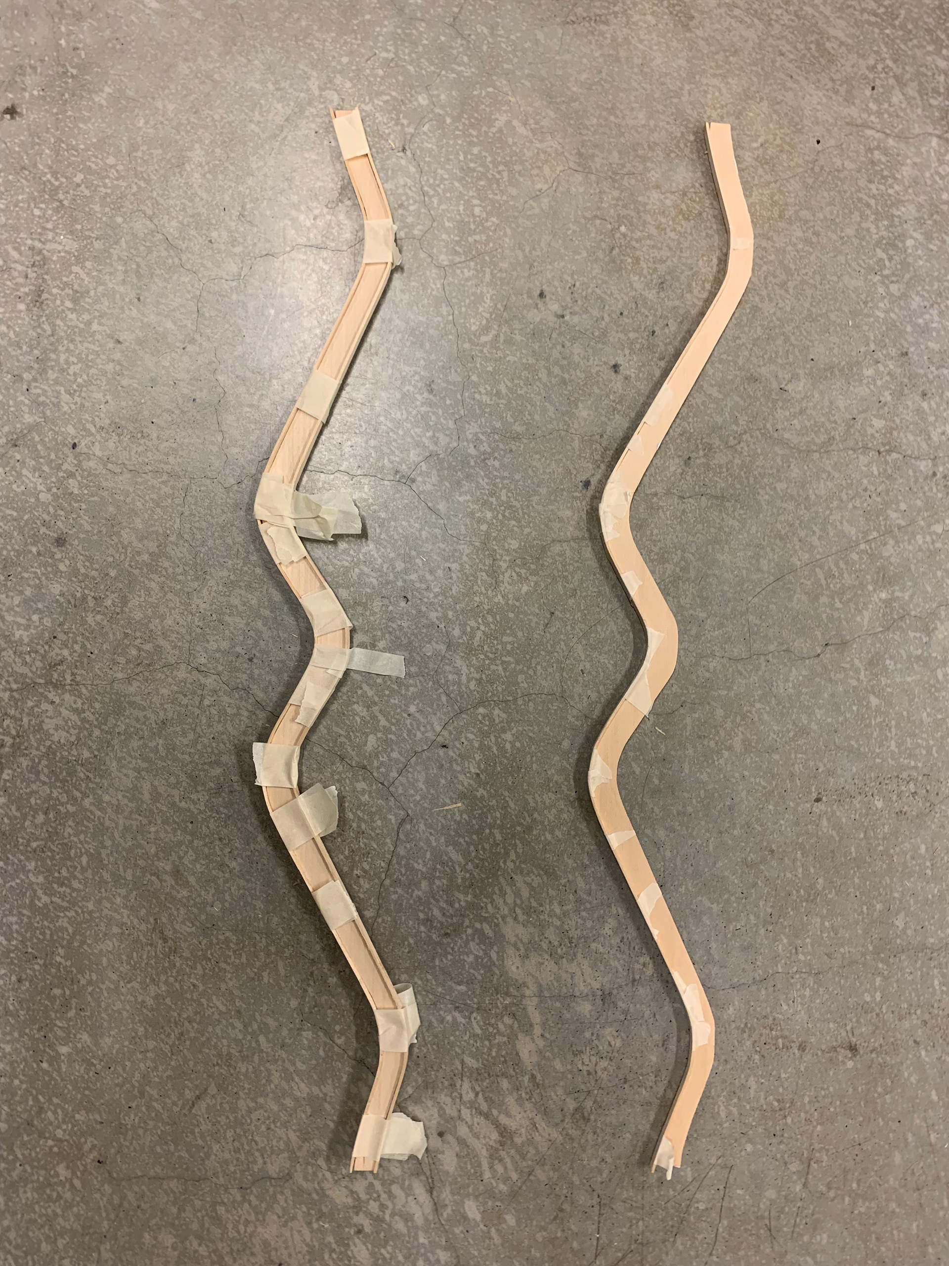
The roof system was constructed using basswood planks that are both laser and hand cut. The vertical strips for the I-Beams are laser cut to achieve the accurate curvatures of the beam, whereas the horizontal strips are cut and then soaked in order allow a more bendables material. After the strips are thoroughly soaked, we molded the strips to the vertical beam by taping them at various points. For the arches, we used a similar fomat of bending and laser cutting, this time without soaking the horizontal strips. In order to make sure the pieces were assembled seamlessly, we glued the arches across the curved beams before attaching them to the H support.
Base and Final Detailing:
For the base, we used foam core to outline the dimensions of the base and casted with rockite the two separate layers. The final details of the model used small scaled pins and cut circular volumes that were then assembled and glued to allow for rolling.
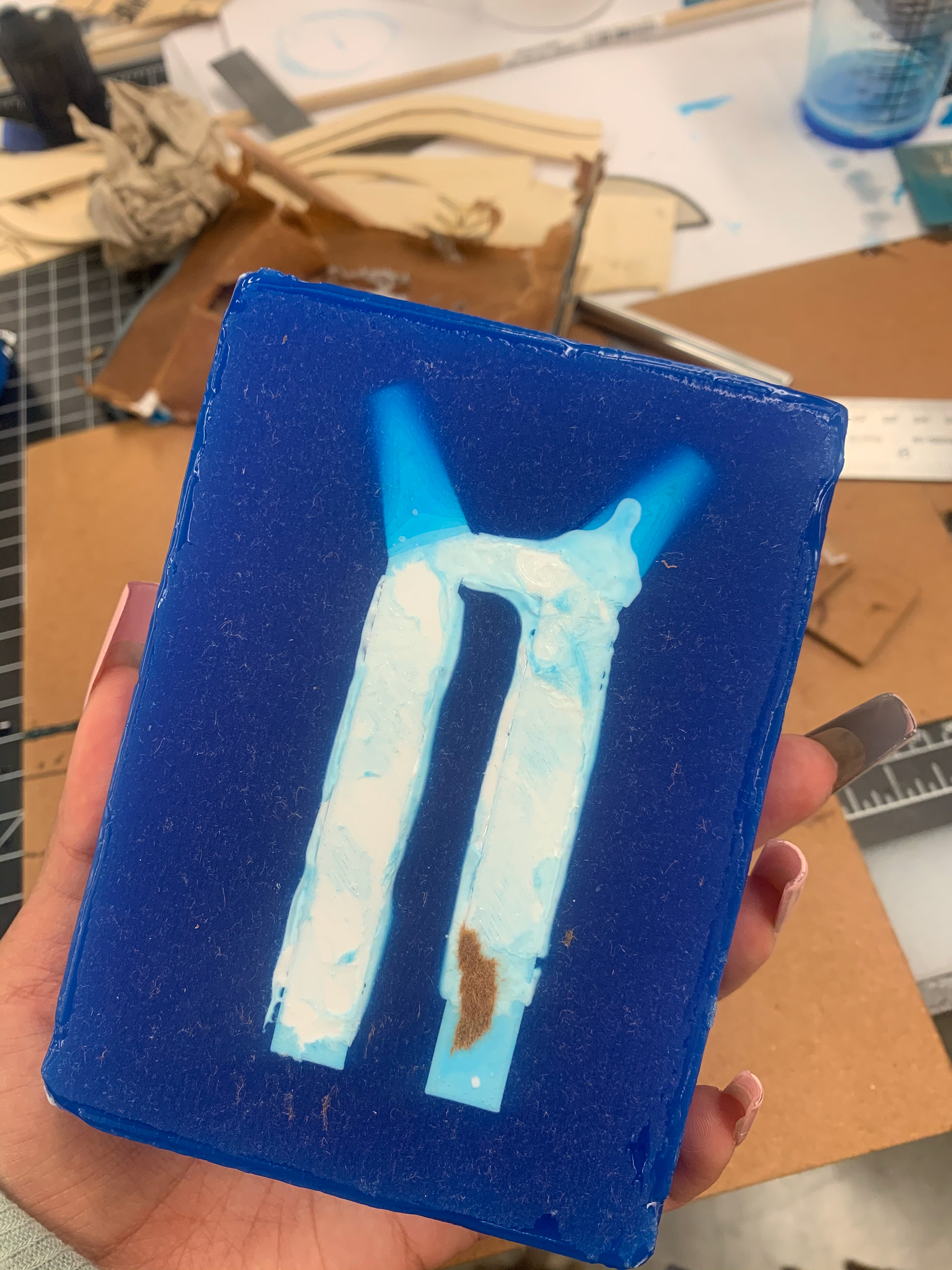
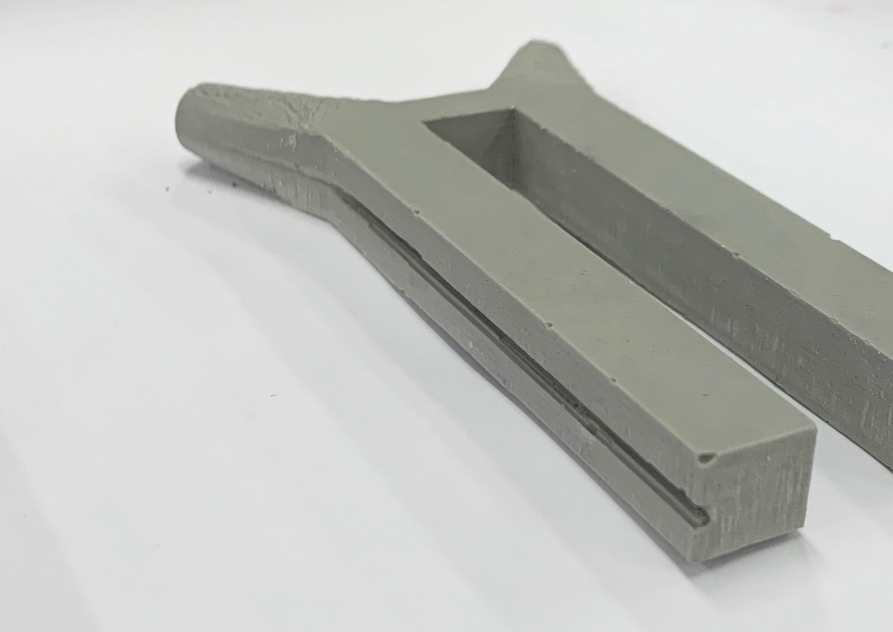
H Concrete Column and Y Supports:
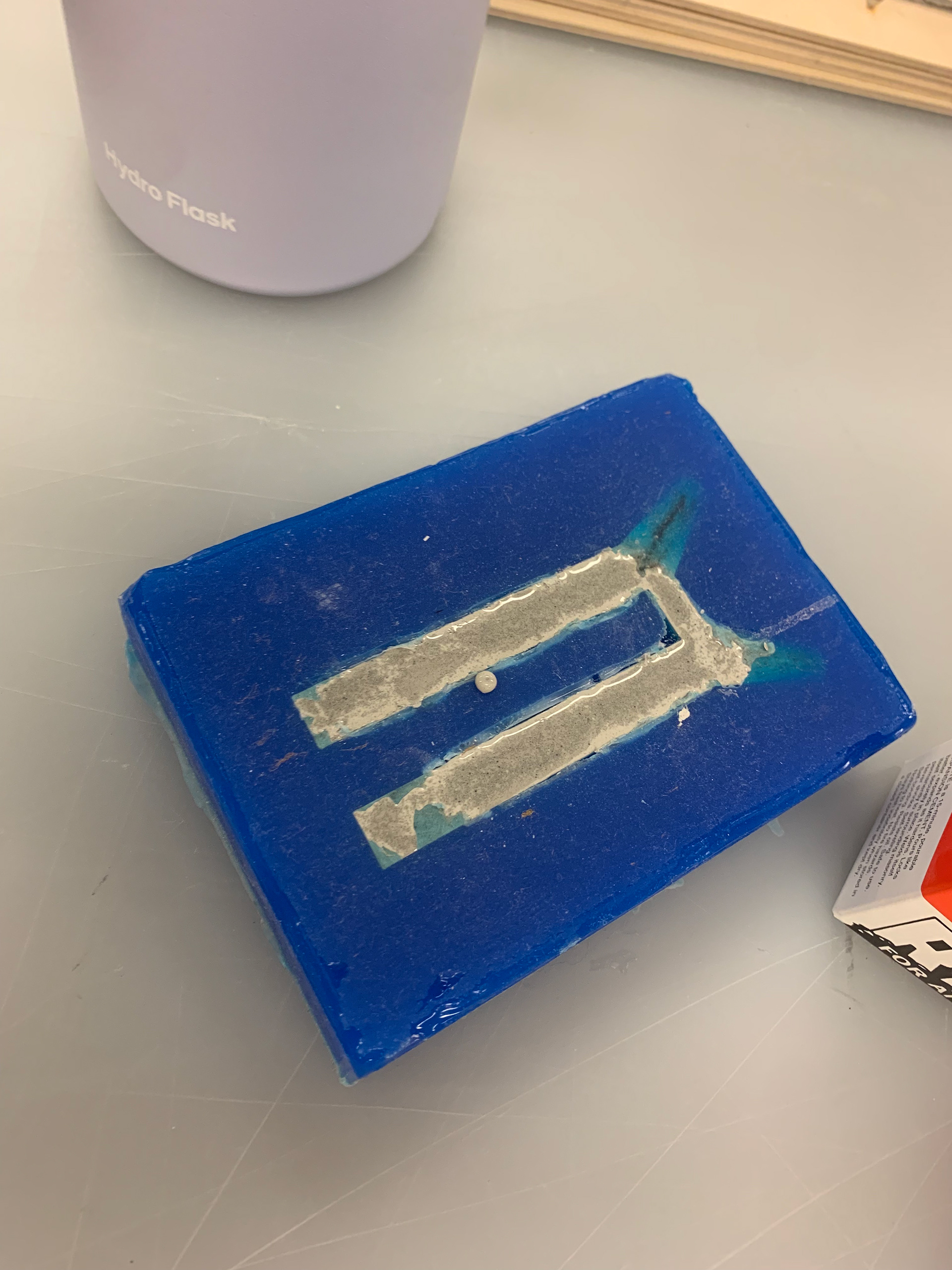
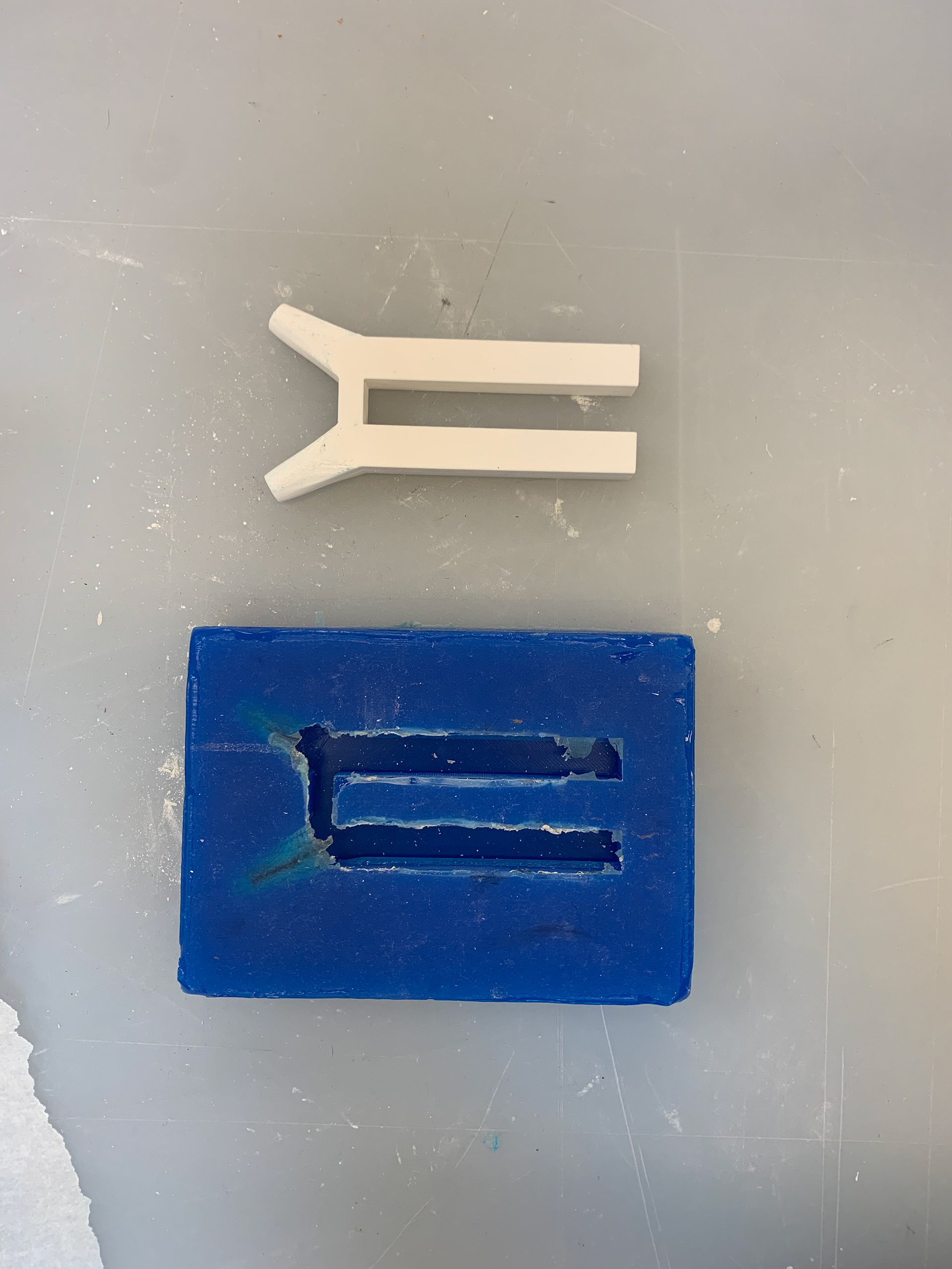
We constructed the H column using a 3-D printed piece that was modeled to the specifics of the structural element in the airport. Once the piece was complete, we set it in a silicone mold, which was then used twice for the rockite bases. This process took two to three days to ensure drying time and durability when taking it out of the mold. The tapered columns that are attached to the H Base were manually sanded then cut in order to create the gradual slendering aspect of the column.
The Y-Supports consisted of 1/8 inch wooden dowels that were doubled and cut at an angle to provide the accurate degree in order to fit on the roof system. The center piece was laser cut and sanded to create another tapered effect.
Process Photos
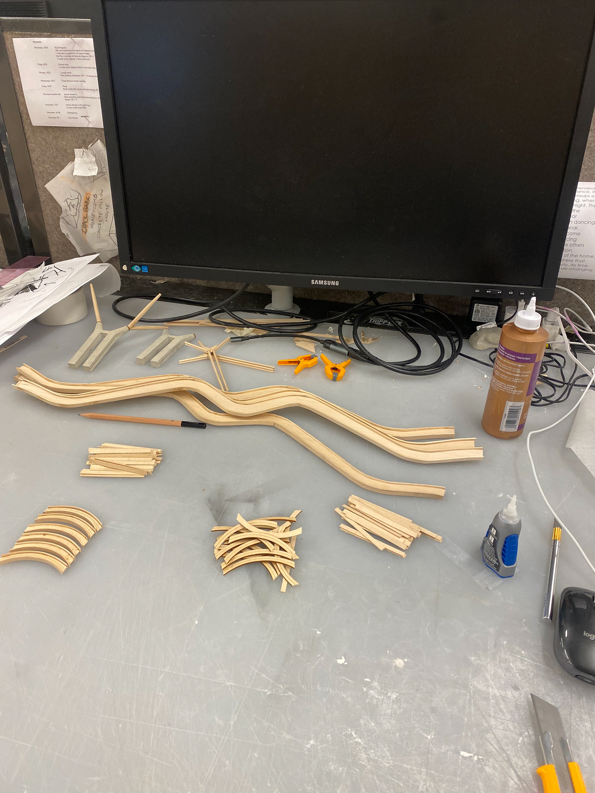
Material and Connection Tests
Creating material tests for the I-beam was imperative to understand the connection between the diagonal pin the connection. Initially, we started laser cutting individual pieces of chipboard and assembling them into the I-beam shape to discover new deatils about the pinned connection to the v-support columns.
After understanding the tectonics of the building we came to the conclusion that in order for the structural integrity of the model to be stable, we are going to have to adjust very minute aspects of the column length and placement. We also decided to use basswood instead of chipboard for the curved i-beams and the arches inbetween all of the beams. To achieve the accurate curvature, we laser cut the vertical piece and soaked the horizontal pieces so that it curves onto the vertical piece. Although in real life there is a pinned connection between the column and the undulating beam, we are going to extend the column into a slot that we created in the beam in order to withstand the load of the modeled roof. We then fabricated the diagonal columns with the tapered ends to see how it would look. This was all done in scale of what the actual model will be (1:10).
Bibliography
“Terminal 4 Madrid-Barajas Airport: An Undulating Roofscape Supported by ArcelorMittal Steel.” Terminal 4 Madrid-Barajas Airport: An Undulating Roofscape Supported by ArcelorMittal Steel, https://constructalia.arcelormittal.com/en/case_study_gallery/spain/terminal_4_madrid_barajas_airport_roofscape_supportet_by_arcelormittal_steel.
“Barajas International Airport Madrid: Rogers Stirk Harbour + Partners, Estudio Lamela, Moso Bamboo Products.” Archello, https://archello.com/project/barajas-international-airport-madrid.
Industrial Sheds in the Port of Avilés: Constructalia. https://constructalia.arcelormittal.com/en/case_study_gallery/spain/industrial_sheds_in_the_port_of_aviles_with_recyclable_steel_structure.
New Terminal Area Madrid-Barajas - Texas A&M University. http://faculty.arch.tamu.edu/anichols/courses/applied-architectural-structures/projects-631/Files/madridairport.pdf.
Villa, Valentina. “Madrid-Barajas Airport Terminal 4 / Estudio Lamela & Rogers Stirk Harbour + Partners.”
ArchDaily, ArchDaily, 10 July 2018, https://www.archdaily.com/805964/madrid-barajas-airport-terminal-4-estudio-lamela-plus-richard-rogers-partnership.
Rogers Stirk Harbour + Partners | RSHP. “Terminal 4, Barajas Airport – Transport – Projects – Rogers Stirk